Chapter 9: Ray Optics and Optical Instruments
In the autumn of 1609, an Italian professor named Galileo Galilei heard of a curious device that had recently been made in the Netherlands — a tube fitted with two glass lenses that made distant objects appear closer. Galileo had never actually seen one. Yet within a matter of days he had ground his own lenses and built a better version of it.
Then he did something that almost no one had thought to do carefully before. Instead of pointing his telescope at ships far out on the horizon, he pointed it up at the night sky.
What he saw changed the way humans understood their place in the universe. The Moon, long believed to be a perfectly smooth sphere, turned out to be covered in mountains and craters. Around the planet Jupiter, four tiny points of light circled steadily, like a miniature solar system. The faint, milky band of the Milky Way broke apart into countless separate stars.
All of this came from nothing more than two pieces of curved glass bending rays of light. The very same rules that make a straw look bent in a glass of water, that can trap light inside a thin glass fibre, and that allow a doctor to look inside the human body, are what allowed Galileo to reach across space with his eyes.
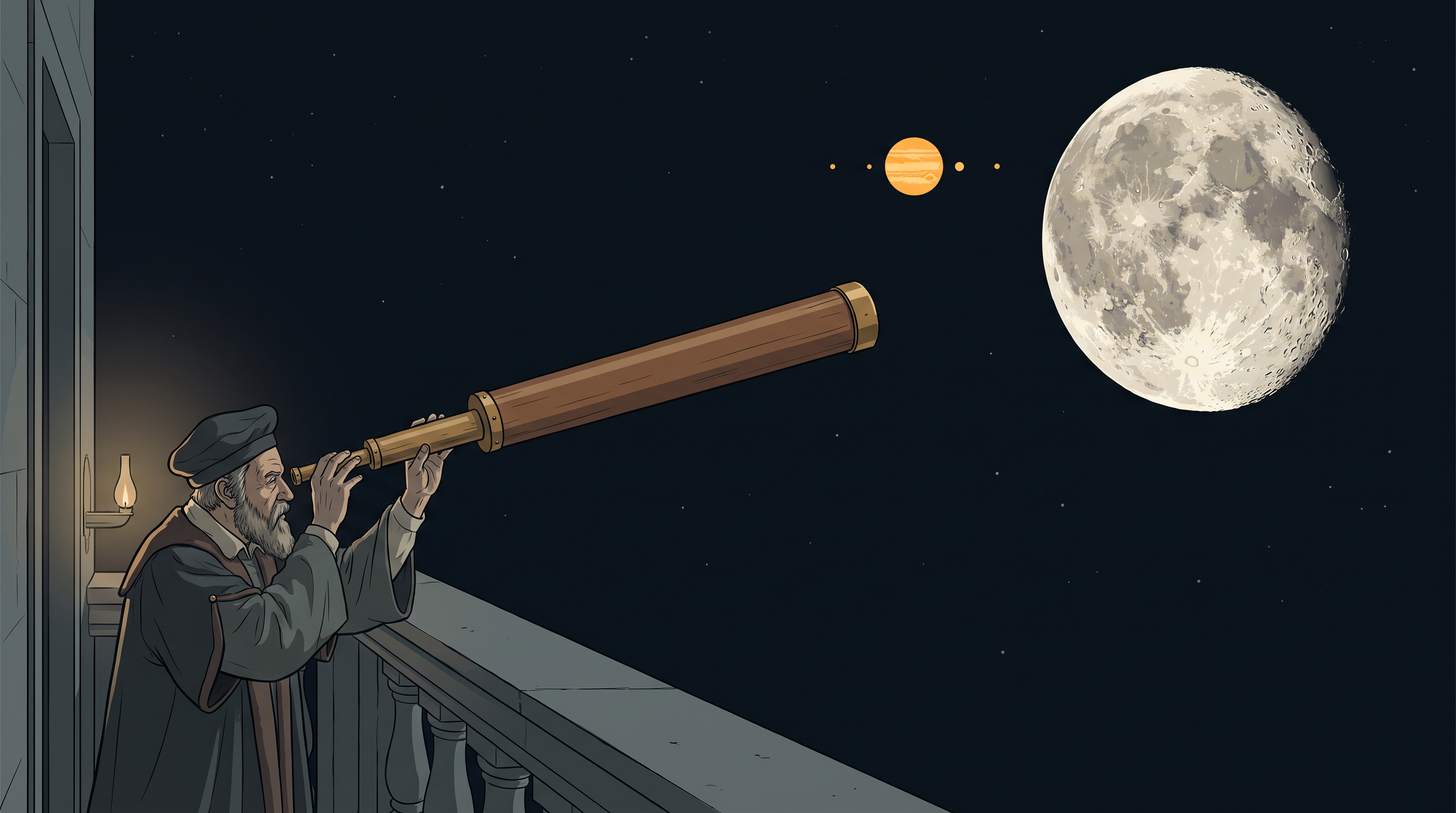
Fig. 9.0 – Galileo and the refracting telescope.
By the end of this chapter, you will be able to answer each of these questions using just a few simple rules about how light travels, bends, and reflects.
9.1 Introduction
Light is our main window to the world. Nature has given the human eye — specifically the light-sensitive layer at its back called the retina — the ability to detect a very small range of electromagnetic waves. Electromagnetic waves are travelling patterns of electric and magnetic fields that you studied in the previous chapter, and they exist over a huge range of wavelengths, from radio waves to gamma rays. This complete range is called the electromagnetic spectrum.
Our eyes respond to only a thin slice of that spectrum — radiation with a wavelength of about 400 nm to 750 nm. This narrow band is what we call light. (The wavelength is the length of one complete cycle of the wave; one nanometre, 1 nm, equals \(10^{-9}\) m.) It is mainly through light, and through our sense of vision, that we come to know and interpret the world around us.
From everyday experience, we can say two simple things about light. First, it travels extremely fast. Second, it appears to travel in a straight line.
It actually took people a long time to realise that the speed of light, though enormous, is finite and can be measured. Its presently accepted value in vacuum is \(c = 2.99792458 \times 10^{8}\ \text{m s}^{-1}\), where \(c\) is the standard symbol for this speed and \(\text{m s}^{-1}\) is its SI unit. For most practical purposes it is enough to round this to \(c = 3 \times 10^{8}\ \text{m s}^{-1}\). (Vacuum here means empty space, with no matter to slow the light down.)
No signal or object has ever been found to move faster than this. The speed of light in vacuum is the highest speed attainable in nature.
There seems to be a problem here. In the previous chapter we learned that light is an electromagnetic wave. Waves usually spread out and bend around obstacles — so how can light also travel neatly in a straight line?
The answer lies in the size of the wavelength. The wavelength of light is extremely small compared with the everyday objects it usually falls on, which are a few centimetres or larger. When the wavelength is this tiny compared to the obstacle, the wave effectively travels from one point to another along the straight line joining those two points. (Exactly why this happens is explained fully in the chapter on wave optics that follows.)
This straight-line path traced by light is called a ray of light. A collection, or bundle, of such rays travelling together is called a beam of light. Picturing light as straight-line rays — the “ray picture” of light — is the foundation of this entire chapter, as suggested in Fig. 9.1a.
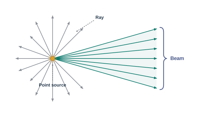
Fig. 9.1a – Rays and a beam of light.
In this chapter we study three ways in which light behaves: reflection (bouncing off a surface), refraction (bending on entering a new transparent medium), and dispersion (splitting into its colours). We treat all of these using the ray picture of light.
Using the basic laws of reflection and refraction, we will learn how images are formed by plane and spherical mirrors and by refracting surfaces and lenses. Building on this, we will then understand the construction and working of several important optical instruments — including the microscope, the telescope, and the most remarkable optical device of all, the human eye.
9.2 Reflection of Light by Spherical Mirrors
You are already familiar with plane mirrors and the laws of reflection from earlier classes. When a ray of light strikes a shiny surface, it bounces back. Let us first restate the two laws that govern this bouncing, because everything in this section rests on them.
The angle of reflection — the angle between the reflected ray and the normal to the surface — is always equal to the angle of incidence — the angle between the incident ray and the normal. Also, the incident ray, the reflected ray, and the normal at the point of incidence all lie in the same plane, as shown in Fig. 9.2. (The normal is simply the line drawn perpendicular to the surface at the point where the ray strikes it.)
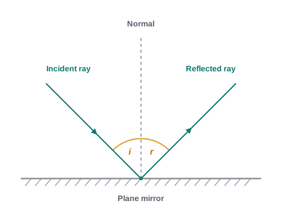
Fig. 9.2 – Reflection of a ray at a plane mirror.
These laws hold at every point of any reflecting surface, whether it is flat or curved. We now focus on the special case of curved reflecting surfaces — specifically spherical surfaces, which are shaped like a small piece cut from a hollow ball.
For a curved surface, we must be careful about what “the normal” means. The normal at any point of a spherical mirror is the perpendicular to the tangent drawn at that point, and this perpendicular always lies along the radius. In other words, the normal is directed along the line joining the centre of curvature of the mirror to the point where the ray strikes.
Let us recall a few terms from earlier study. The geometric centre of a spherical mirror is called its pole (P). The centre of the sphere of which the mirror forms a part is the centre of curvature (C), and the radius of that sphere is the radius of curvature (R). The straight line joining the pole and the centre of curvature is called the principal axis of the mirror.
For a spherical lens, the corresponding central point is called the optical centre rather than the pole; the principal axis of a lens is the line joining its optical centre with its principal focus, which we will meet later.
9.2.1 Sign convention
Before we can derive formulae that relate object distance, image distance, and focal length, we need a consistent way of labelling distances as positive or negative. Without such a rule, the same formula would have to be rewritten for every different situation.
In this book we use the Cartesian sign convention. According to it, all distances are measured from the pole of the mirror (or the optical centre of the lens), treating that point like the origin of a graph.
Distances measured in the same direction as the incident light are taken as positive, and distances measured in the direction opposite to the incident light are taken as negative, as shown in Fig. 9.3.
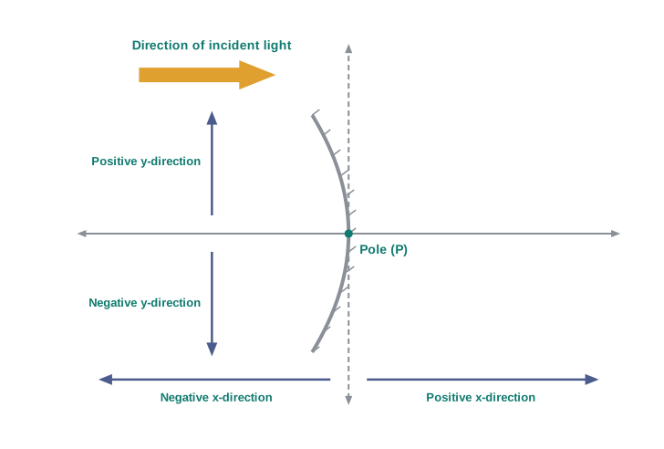
Fig. 9.3 – The Cartesian sign convention.
Similarly, heights measured upwards — perpendicular to the principal axis and above the x-axis — are taken as positive, while heights measured downwards are taken as negative.
The great advantage of adopting one accepted convention is that a single formula for spherical mirrors, and a single formula for spherical lenses, can then handle every possible case — concave or convex, real image or virtual image — without any change.
9.2.2 Focal length of spherical mirrors
Figure 9.4 shows what happens when a parallel beam of light falls on (a) a concave mirror and (b) a convex mirror. We assume the rays are paraxial — that is, they strike the mirror at points close to the pole P and make only small angles with the principal axis.
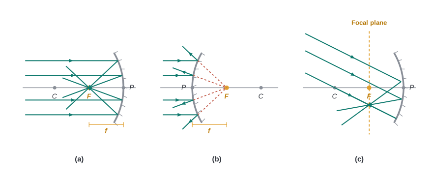
Fig. 9.4 – Principal focus and focal plane of spherical mirrors.
For a concave mirror, the reflected rays actually converge to a single point F on the principal axis [Fig. 9.4(a)]. For a convex mirror, the reflected rays spread apart, but when produced backwards they appear to come from a point F behind the mirror on the principal axis [Fig. 9.4(b)]. This point F is called the principal focus of the mirror.
If instead the parallel beam arrives making some angle with the principal axis, the reflected rays meet (or appear to diverge from) a point lying in a plane that passes through F and is perpendicular to the principal axis. This plane is called the focal plane of the mirror [Fig. 9.4(c)].
The distance between the focus F and the pole P is called the focal length of the mirror, denoted by \(f\).
We can now prove a very useful result: the focal length is half the radius of curvature, that is \(f = R/2\). The geometry of the reflection of a single ray is shown in Fig. 9.5.
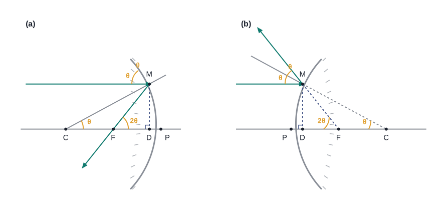
Fig. 9.5 – Geometry for the relation f = R/2.
Let C be the centre of curvature. Consider a ray parallel to the principal axis that strikes the mirror at the point M. Since CM is a radius, it is perpendicular (normal) to the mirror at M. Let θ be the angle of incidence, and let MD be the perpendicular dropped from M onto the principal axis.
From the geometry of the figure (the reflected ray makes the same angle θ with the normal, and using the exterior-angle property of the triangles), we obtain \[\angle \text{MCP} = \theta \quad \text{and} \quad \angle \text{MFP} = 2\theta\]
From the two right-angled triangles in the figure, \[\tan\theta = \frac{\text{MD}}{\text{CD}} \quad \text{and} \quad \tan 2\theta = \frac{\text{MD}}{\text{FD}} \tag{9.1}\]
For paraxial rays, θ is small, so we may use the approximations \(\tan\theta \approx \theta\) and \(\tan 2\theta \approx 2\theta\). Putting these into Eq. (9.1) gives \[\frac{\text{MD}}{\text{FD}} = 2\,\frac{\text{MD}}{\text{CD}}\] \[\text{or,} \quad \text{FD} = \frac{\text{CD}}{2} \tag{9.2}\]
Now, because θ is small, the point D lies very close to the pole P. Therefore we may take \(\text{FD} = f\) (the focal length) and \(\text{CD} = R\) (the radius of curvature). Equation (9.2) then gives \[f = \frac{R}{2} \tag{9.3}\]
Here \(f\) is the focal length and \(R\) the radius of curvature, both measured in metres (m).
A word of caution: Eq. (9.3) is exact only for paraxial rays. Rays striking far from the pole do not all meet at the same point — this defect blurs the focus of a wide mirror, and it is one reason we insist on the paraxial (small-angle) assumption throughout this chapter.
9.2.3 The mirror equation
When rays coming from a point actually meet at another point after reflection (and/or refraction), that meeting point is called the image of the first point. The image is called real if the rays truly converge to it, and virtual if the rays do not actually meet but only appear to diverge from it when produced backwards. An image is thus a point-to-point copy of the object created by reflection or refraction.
In principle, to locate the image of any point we could trace any two rays from it and find where they cross. In practice, it is convenient to choose two of the following four rays, whose behaviour we already know:
A ray parallel to the principal axis. After reflection it passes through the focus (concave mirror), or appears to come from the focus (convex mirror).
A ray passing through the centre of curvature of a concave mirror (or directed towards it for a convex mirror). It strikes the mirror normally and simply retraces its path.
A ray passing through (or directed towards) the focus. After reflection it travels parallel to the principal axis.
A ray incident at any angle at the pole. It reflects following the laws of reflection, with the principal axis acting as the normal.
Figure 9.6 uses three of these rays to locate the image A’B’ (here a real image) of an object AB placed in front of a concave mirror.

Fig. 9.6 – Ray diagram for a concave mirror forming a real image.
It is important to realise that only three rays are drawn for convenience; in reality an infinite number of rays leave each point of the object in all directions. Point A’ is the image of point A precisely because every ray that leaves A and reflects off the mirror passes through A’.
We now derive the mirror equation — the relation connecting the object distance (\(u\)), the image distance (\(v\)), and the focal length (\(f\)).
From Fig. 9.6, the two right-angled triangles A’B’F and MPF are similar. (For paraxial rays, MP can be treated as a straight line perpendicular to the principal axis, so that MP = AB.) Therefore \[\frac{\text{B}'\text{A}'}{\text{PM}} = \frac{\text{B}'\text{F}}{\text{FP}}\] \[\text{or} \quad \frac{\text{B}'\text{A}'}{\text{BA}} = \frac{\text{B}'\text{F}}{\text{FP}} \quad (\because \text{PM} = \text{AB}) \tag{9.4}\]
Also, since \(\angle \text{APB} = \angle \text{A}'\text{PB}'\) (the incident and reflected rays at the pole make equal angles with the axis), the right-angled triangles A’B’P and ABP are similar. Therefore \[\frac{\text{B}'\text{A}'}{\text{BA}} = \frac{\text{B}'\text{P}}{\text{BP}} \tag{9.5}\]
Comparing Eqs. (9.4) and (9.5), \[\frac{\text{B}'\text{F}}{\text{FP}} = \frac{\text{B}'\text{P} - \text{FP}}{\text{FP}} = \frac{\text{B}'\text{P}}{\text{BP}} \tag{9.6}\]
So far Eq. (9.6) involves only the magnitudes of distances. We now apply the sign convention. Light travels from the object to the mirror MPN, so that direction is positive. To go from the pole P back to the object AB, the image A’B’, and the focus F, we must travel opposite to the incident light — so all three of these distances are negative. Thus \[\text{B}'\text{P} = -v, \quad \text{FP} = -f, \quad \text{BP} = -u\]
Substituting these into Eq. (9.6), \[\frac{-v + f}{-f} = \frac{-v}{-u}\] \[\text{or} \quad \frac{v - f}{f} = \frac{v}{u}\] \[\frac{v}{f} = 1 + \frac{v}{u}\]
Dividing throughout by \(v\), we obtain \[\frac{1}{v} + \frac{1}{u} = \frac{1}{f} \tag{9.7}\]
This important relation is known as the mirror equation. Here \(u\) is the object distance, \(v\) the image distance, and \(f\) the focal length, all measured from the pole (in metres, m) and carrying their proper signs.
The size of the image compared with the object is described by the linear magnification (m), defined as the ratio of the height of the image (\(h'\)) to the height of the object (\(h\)): \[m = \frac{h'}{h} \tag{9.8}\]
Both \(h\) and \(h'\) carry signs according to the convention (upward positive, downward negative). From the similar triangles A’B’P and ABP, \(\dfrac{\text{B}'\text{A}'}{\text{BA}} = \dfrac{\text{B}'\text{P}}{\text{BP}}\). Applying the sign convention, this becomes \[\frac{-h'}{h} = \frac{-v}{-u}\] so that \[m = \frac{h'}{h} = -\frac{v}{u} \tag{9.9}\]
Although we derived Eqs. (9.7) and (9.9) for the case of a real, inverted image formed by a concave mirror, they are in fact valid for every case of reflection by a spherical mirror — concave or convex, and whether the image is real or virtual — provided the sign convention is applied correctly. Figure 9.7 shows the ray diagrams for a virtual image formed by (a) a concave mirror (object between P and F) and (b) a convex mirror; you should verify for yourself that Eqs. (9.7) and (9.9) hold in these cases too.
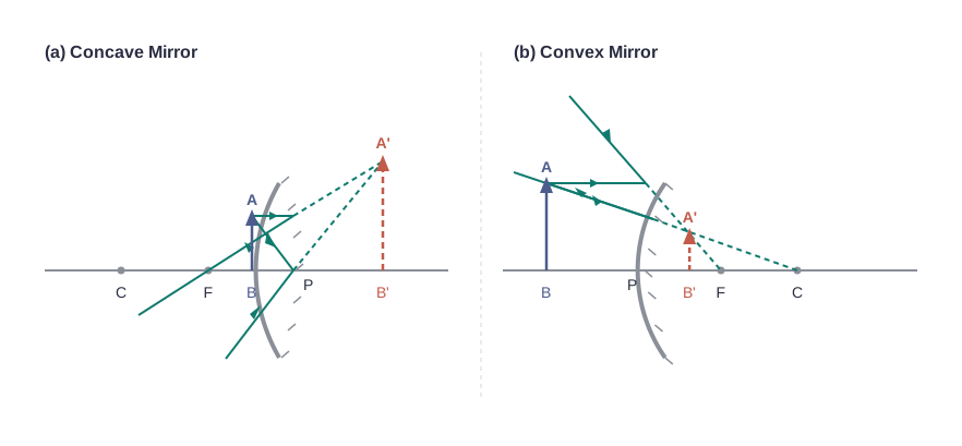
Fig. 9.7 – Virtual image formation by spherical mirrors.
This single pair of equations, together with the sign convention, is exactly what allows one curved mirror to produce so many different kinds of image — enlarged or diminished, upright or inverted, real or virtual — simply by changing where the object is placed.
A mobile phone lies along the principal axis of a concave mirror, as shown in Fig. 9.8. By drawing a suitable ray diagram, show how its image is formed. Explain why the magnification is not uniform. Will the amount of distortion depend on where the phone is placed relative to the mirror?
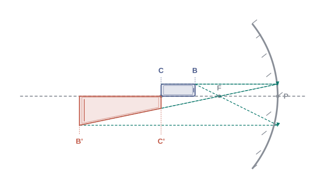
[Caption:] Fig. 9.8 – Distorted image of an object along the principal axis. [/Caption:]
Solution: The ray diagram for the image of the phone is shown in Fig. 9.8. The part of the phone lying in a plane perpendicular to the principal axis is imaged in that same plane and keeps its size, so \(\text{B}'\text{C} = \text{BC}\). However, the part of the phone lying along the axis is imaged with a different magnification, because different points along its length are at different distances from the mirror. Since magnification depends on distance, that part of the image is stretched unevenly, and the image therefore appears distorted. For the same reason, the degree of distortion does depend on where the phone is placed with respect to the mirror.
9.3 Refraction
When a beam of light meets the surface of another transparent medium — say, when a ray in air arrives at the surface of glass or water — two things happen at once. Part of the light is reflected back into the first medium, and the rest passes on into the second medium. Since a single ray of light stands for a whole beam, we can follow just one ray to understand this.
If the ray strikes the surface obliquely — that is, at any angle of incidence between \(0^\circ\) and \(90^\circ\) (written \(0^\circ < i < 90^\circ\)) — then the ray that enters the second medium changes its direction at the boundary between the two media. This bending of light as it passes from one transparent medium into another is called refraction of light. The boundary itself is called the interface.
Why does the ray bend at all? Light travels at different speeds in different media, and it is this change of speed at the interface that forces the ray to change direction. When light slows down on entering a new medium, it bends towards the normal; when it speeds up, it bends away from the normal. (Recall that the normal is the perpendicular drawn to the surface at the point where the ray strikes.)
The scientist Snell found, by careful experiment, the two rules that govern refraction. They are known as the laws of refraction:
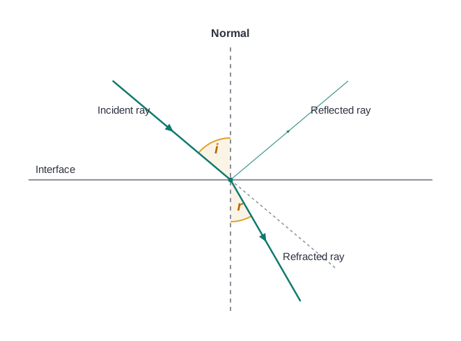
Fig. 9.9 – Refraction and partial reflection at an interface.
The first law states that the incident ray, the refracted ray, and the normal to the interface at the point of incidence all lie in the same plane.
The second law states that, for a given pair of media, the ratio of the sine of the angle of incidence to the sine of the angle of refraction is a constant. Here the angle of incidence (\(i\)) and the angle of refraction (\(r\)) are the angles that the incident ray and the refracted ray respectively make with the normal. In symbols, \[\frac{\sin i}{\sin r} = n_{21} \tag{9.10}\]
The constant \(n_{21}\) is called the refractive index of the second medium with respect to the first medium. Equation (9.10) is the well-known Snell’s law of refraction.
Note two things about \(n_{21}\). It is a characteristic of the particular pair of media (and it also depends slightly on the wavelength, that is, the colour, of the light — a fact that becomes important when we study dispersion). But it does not depend on the angle of incidence: the same value works for every angle.
Let us read off what Eq. (9.10) tells us. If \(n_{21} > 1\), then \(r < i\), so the refracted ray bends towards the normal. In this case medium 2 is said to be optically denser (or simply denser) than medium 1. On the other hand, if \(n_{21} < 1\), then \(r > i\), and the refracted ray bends away from the normal — this is what happens when a ray travelling in a denser medium refracts out into a rarer medium.
There is a neat relation between the two refractive indices of a pair of media. If \(n_{21}\) is the refractive index of medium 2 with respect to medium 1, and \(n_{12}\) is the refractive index of medium 1 with respect to medium 2, then they are simply reciprocals of each other: \[n_{12} = \frac{1}{n_{21}} \tag{9.11}\]
It also follows that if \(n_{32}\) is the refractive index of medium 3 with respect to medium 2, then \[n_{32} = n_{31} \times n_{12}\] where \(n_{31}\) is the refractive index of medium 3 with respect to medium 1. This lets us relate three media through a common reference.
A few simple and familiar results follow at once from the laws of refraction.
Consider a rectangular glass slab. A ray entering it refracts twice — once at the air-glass face and once at the glass-air face. As Fig. 9.10 shows, it turns out that \(r_2 = i_1\); that is, the emergent ray comes out parallel to the incident ray. So the slab produces no net change in direction, but the emergent ray is shifted sideways relative to the incident ray. This sideways shift is called the lateral displacement (or lateral shift).
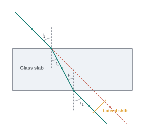
Fig. 9.10 – Lateral displacement through a glass slab.
Another everyday observation is that the bottom of a tank filled with water appears to be raised — the water looks shallower than it really is, as shown in Fig. 9.11. For viewing close to the normal (that is, looking almost straight down), it can be shown that the apparent depth is the real depth divided by the refractive index of the medium: \[\text{apparent depth } (h_1) = \frac{\text{real depth } (h_2)}{n}\] Here \(h_1\) is the apparent (reduced) depth, \(h_2\) is the true depth, and \(n\) is the refractive index of the liquid (water).
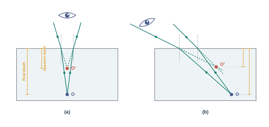
Fig. 9.11 – Apparent depth of an object in water.
Both of these effects come from the same simple idea. Light rays from the straw or the tank bottom bend as they leave the water and enter the air, so they reach our eyes travelling along slightly different directions than they started with. Our eyes and brain assume light travels in straight lines, so they trace the rays straight back — and place the object where the rays appear to come from. That is why a straw standing in water looks bent at the surface, and why a swimming pool always looks shallower than it truly is.
9.4 Total Internal Reflection
We saw in the previous section that when light passes from a denser medium into a rarer one, it bends away from the normal. Something remarkable can happen in this situation, and this section explores it.
Whenever light reaches the boundary between two media, part of it is reflected back into the first medium and part is refracted into the second. When the light happens to be travelling in the denser medium and meets the boundary with a rarer medium, the reflection back into the denser medium is called internal reflection.
Let us follow what happens as we steadily increase the angle of incidence. Consider a point A inside a denser medium (water) sending out rays that strike the water-air surface at larger and larger angles, as shown in Fig. 9.12.
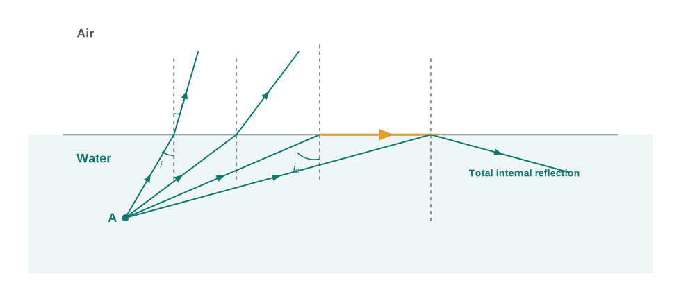
Fig. 9.12 – Total internal reflection at a water–air interface.
Take the ray AO₁B. At the surface it is partly reflected back into the water (as O₁C) and partly refracted into the air (as O₁B). Because the ray is going from a denser to a rarer medium, the angle of refraction (\(r\)) is larger than the angle of incidence (\(i\)).
As we increase the angle of incidence, the angle of refraction increases too. Eventually, for a particular ray (AO₃ in the figure), the angle of refraction becomes \(90^\circ\) (that is, \(\pi/2\)). The refracted ray is now bent so far from the normal that it just grazes along the surface between the two media — this is the ray AO₃D.
If we increase the angle of incidence even a little more (as for ray AO₄), refraction becomes impossible. The whole of the light is now reflected back into the denser medium. This complete reflection is called total internal reflection.
There is an important difference between total internal reflection and ordinary reflection at a mirror. In ordinary reflection, some fraction of the light is always transmitted through the surface, so the reflected ray is always a little less intense than the incident ray, no matter how smooth the surface is. In total internal reflection, by contrast, no light at all is transmitted — the reflection is total, and none of the energy is lost to the second medium.
The special angle of incidence at which the angle of refraction is exactly \(90^\circ\) (the angle ∠AO₃N in Fig. 9.12) is called the critical angle, written \(i_c\), for the given pair of media.
We can find \(i_c\) directly from Snell’s law, Eq. (9.10). When light goes from the denser medium into the rarer one, the relative refractive index of the refracting (rarer) medium is less than one. Since the largest possible value of \(\sin r\) is \(1\) (when \(r = 90^\circ\)), there is an upper limit to \(\sin i\) for which Snell’s law can still be satisfied. That limit occurs at \(i = i_c\), giving \[\sin i_c = n_{21} \tag{9.12}\] where \(n_{21}\) is the refractive index of the rarer medium with respect to the denser one.
For any angle of incidence larger than \(i_c\), Snell’s law simply cannot be satisfied, so no refraction is possible — and total internal reflection takes over.
The refractive index of the denser medium 1 with respect to the rarer medium 2 can then be written as \(n_{12} = 1/\sin i_c\). Some typical critical angles (measured with respect to air) are listed in Table 9.1.
Table 9.1 — Critical angle of some transparent media with respect to air
| Substance medium | Refractive index | Critical angle |
|---|---|---|
| Water | 1.33 | 48.75 |
| Crown glass | 1.52 | 41.14 |
| Dense flint glass | 1.62 | 37.31 |
| Diamond | 2.42 | 24.41 |
A demonstration for total internal reflection
Total internal reflection can be shown very simply using a laser torch or pointer, which is easily available today. Take a glass beaker with clear water and add a few drops of milk (or any similar suspension), then stir, so that the water becomes slightly turbid. When you shine the laser through this turbid water, the path of the beam glows brightly, so you can actually see where the light goes.
First, shine the beam from below the beaker so that it strikes the upper water surface at the far end. You will see that it undergoes partial reflection (a spot appears on the table below) and partial refraction (a spot appears on the roof, from the light that escapes into the air), as in Fig. 9.13(a).
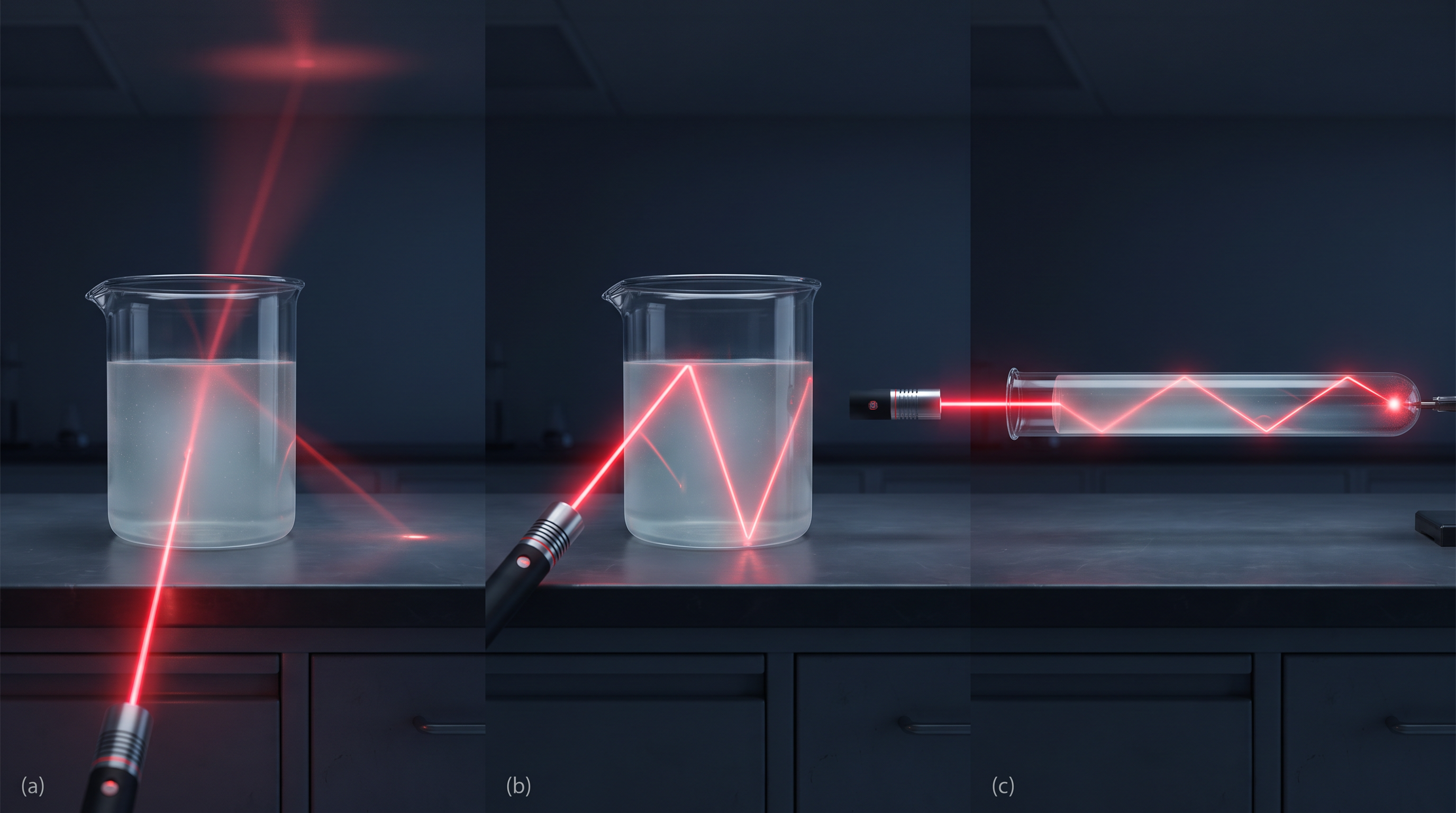
Fig. 9.13 – Total internal reflection of a laser beam in water.
Now direct the laser beam from one side so that it meets the upper surface more obliquely, as in Fig. 9.13(b). Slowly adjust the direction until you reach the angle at which the refracted beam above the water vanishes completely and all the light is reflected back into the water. That is total internal reflection at its simplest.
Finally, pour the water into a long test tube and shine the laser in from the top, as in Fig. 9.13(c). By adjusting the beam so that it is totally internally reflected every time it hits the walls, you can make the light travel down the tube. This is very close to what happens inside an optical fibre.
A word of caution while doing this: never look directly into the laser beam, and never point it at anyone’s face.
9.4.1 Total internal reflection in nature and its technological applications
(i) Prism. A prism is a block of glass, usually triangular, that can bend and redirect light. Prisms can be designed to turn light through \(90^\circ\) or through \(180^\circ\) using total internal reflection [Fig. 9.14(a) and (b)]. Such a prism can also be used to invert an image without changing its size [Fig. 9.14(c)]. For the first two cases to work, the critical angle \(i_c\) of the prism material must be less than \(45^\circ\); from Table 9.1 you can check that this is true for both crown glass and dense flint glass. (We will study refraction through a prism in detail in a later section.)
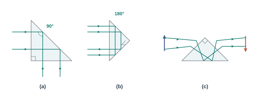
Fig. 9.14 – Redirecting and inverting light using prisms.
(ii) Optical fibres. Optical fibres are today used widely to carry audio and video signals over long distances, and they work entirely on total internal reflection. An optical fibre is made from high-quality composite glass or quartz. Each fibre has two parts: an inner core and an outer layer called the cladding. The key point is that the refractive index of the core is higher than that of the cladding, so the core is the denser medium.
When a light signal is fed into one end of the fibre at a suitable angle, it strikes the core-cladding boundary at an angle greater than the critical angle, and so it undergoes total internal reflection. It reflects again and again down the length of the fibre and finally emerges at the other end, as shown in Fig. 9.15. Because the reflection is total at every bounce, there is no appreciable loss of intensity along the way.
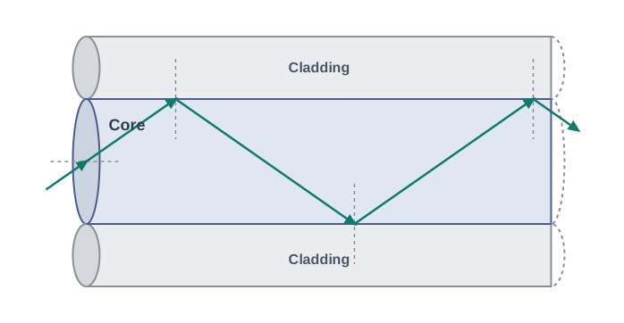
Fig. 9.15 – Total internal reflection in an optical fibre.
The fibre is made so that light reflected off one side of the inner surface always strikes the other side at an angle larger than the critical angle. Because of this, the light stays trapped inside the core even when the fibre is bent — it simply keeps bouncing and follows the fibre around the curve. In this way an optical fibre behaves like an “optical pipe” that carries light from one end to the other. This is exactly how light is made to travel along a long, thin, even bent fibre without leaking out.
A bundle of such fibres has many uses. Optical fibres are widely used to transmit and receive electrical signals after they are converted into light by suitable devices called transducers, and they can of course also carry optical signals directly.
The main requirement in making good optical fibres is that the light should be absorbed as little as possible over long distances. This has been achieved by highly purifying and specially preparing materials such as quartz. In silica glass fibres, it is now possible to transmit more than 95% of the light over a fibre length of 1 km — far better than an ordinary window-glass block of the same thickness would allow.
9.5 Refraction at Spherical Surfaces and by Lenses
Up to now we have studied refraction only at a flat (plane) surface. We now turn to refraction at a curved surface — a spherical interface separating two transparent media. This is the key step that will lead us to lenses.
The trick is to notice that a very small piece of a spherical surface can be treated as almost flat, so the same laws of refraction can be applied at every point of it. Exactly as with a spherical mirror, the normal at the point of incidence is perpendicular to the surface there, and therefore points along the line through the centre of curvature.
We first work out image formation by a single spherical refracting surface. We then treat a thin lens, which is simply a transparent medium bounded by two surfaces, at least one of which is spherical. By applying the single-surface result at each of the two surfaces of a lens in turn, we will arrive first at the lens maker’s formula and then at the lens formula.
9.5.1 Refraction at a spherical surface
Figure 9.16 shows how an image I of a point object O, lying on the principal axis, is formed by a single spherical refracting surface. The surface has centre of curvature C and radius of curvature R. Light travels from a medium of refractive index \(n_1\) into a medium of refractive index \(n_2\).
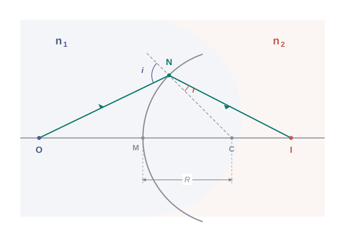
Fig. 9.16 – Refraction at a spherical surface.
As before, we assume the aperture (the width) of the surface is small compared with the other distances, so all angles are small and we can use the small-angle approximation. In particular, the height NM is taken to be nearly equal to the perpendicular from the point N onto the principal axis. For small angles, we can write the tangents of the angles as \[\tan \angle \text{NOM} = \frac{\text{MN}}{\text{OM}}, \qquad \tan \angle \text{NCM} = \frac{\text{MN}}{\text{MC}}, \qquad \tan \angle \text{NIM} = \frac{\text{MN}}{\text{MI}}\]
Now, for the triangle NOC, the angle \(i\) is the exterior angle, and an exterior angle equals the sum of the two opposite interior angles. Therefore \(i = \angle \text{NOM} + \angle \text{NCM}\), giving \[i = \frac{\text{MN}}{\text{OM}} + \frac{\text{MN}}{\text{MC}} \tag{9.13}\]
Similarly, from the geometry, \(r = \angle \text{NCM} - \angle \text{NIM}\), that is, \[r = \frac{\text{MN}}{\text{MC}} - \frac{\text{MN}}{\text{MI}} \tag{9.14}\]
By Snell’s law, \(n_1 \sin i = n_2 \sin r\), and for small angles this becomes simply \[n_1 i = n_2 r\]
Substituting the values of \(i\) and \(r\) from Eqs. (9.13) and (9.14) into this, and simplifying, we obtain \[\frac{n_1}{\text{OM}} + \frac{n_2}{\text{MI}} = \frac{n_2 - n_1}{\text{MC}} \tag{9.15}\]
So far OM, MI, and MC stand for magnitudes of distances. Applying the Cartesian sign convention (measuring from the point M, with distances against the incident light taken negative), \[\text{OM} = -u, \qquad \text{MI} = +v, \qquad \text{MC} = +R\]
Putting these into Eq. (9.15) gives the important result \[\frac{n_2}{v} - \frac{n_1}{u} = \frac{n_2 - n_1}{R} \tag{9.16}\]
Equation (9.16) connects the object distance \(u\) and image distance \(v\) to the refractive indices of the two media and the radius of curvature \(R\) of the surface. It holds for any single curved spherical refracting surface.
9.5.2 Refraction by a lens
Figure 9.17(a) shows how a double convex lens forms an image. We can understand it in two steps.
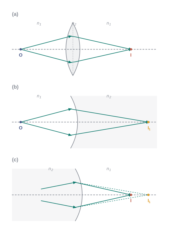
Fig. 9.17 – Two-step image formation by a lens.
Step 1. The first refracting surface forms an image \(I_1\) of the object O [Fig. 9.17(b)]. Applying Eq. (9.15) to this first interface ABC, \[\frac{n_1}{\text{OB}} + \frac{n_2}{\text{BI}_1} = \frac{n_2 - n_1}{\text{BC}_1} \tag{9.17}\]
Step 2. This image \(I_1\) now acts as a virtual object for the second surface, which forms the final image at I [Fig. 9.17(c)]. Applying the same relation to the second interface ADC (noting that here the light now travels from the glass, index \(n_2\), back out into air, index \(n_1\)), \[-\frac{n_2}{\text{DI}_1} + \frac{n_1}{\text{DI}} = \frac{n_2 - n_1}{\text{DC}_2} \tag{9.18}\]
For a thin lens, the two surfaces are very close, so \(\text{BI}_1 = \text{DI}_1\). Adding Eqs. (9.17) and (9.18), the \(I_1\) terms cancel, and we get \[\frac{n_1}{\text{OB}} + \frac{n_1}{\text{DI}} = (n_2 - n_1)\left(\frac{1}{\text{BC}_1} + \frac{1}{\text{DC}_2}\right) \tag{9.19}\]
Now suppose the object is placed at infinity, so \(\text{OB} \to \infty\) and the image forms at the focus, \(\text{DI} = f\). Then Eq. (9.19) becomes \[\frac{n_1}{f} = (n_2 - n_1)\left(\frac{1}{\text{BC}_1} + \frac{1}{\text{DC}_2}\right) \tag{9.20}\]
The point where light from an object at infinity is brought to a focus is called the focus F of the lens, and the distance \(f\) is its focal length. A lens has two foci, F and F’, one on each side (Fig. 9.18).
Applying the sign convention, \(\text{BC}_1 = +R_1\) and \(\text{DC}_2 = -R_2\). With these, and writing \(n_{21} = n_2/n_1\), Eq. (9.20) takes the well-known form \[\frac{1}{f} = (n_{21} - 1)\left(\frac{1}{R_1} - \frac{1}{R_2}\right) \qquad \left(\because n_{21} = \frac{n_2}{n_1}\right) \tag{9.21}\]
Equation (9.21) is the lens maker’s formula. It is extremely useful, because it lets a lens designer choose the radii \(R_1\) and \(R_2\) needed to produce any desired focal length. The formula also works for a concave lens: in that case \(R_1\) is negative and \(R_2\) positive, so \(f\) comes out negative.
Combining Eqs. (9.19) and (9.20) gives \[\frac{n_1}{\text{OB}} + \frac{n_1}{\text{DI}} = \frac{n_1}{f} \tag{9.22}\]
In the thin-lens approximation, the points B and D both lie close to the optical centre of the lens — the central point through which a ray passes without bending. Applying the sign convention \(\text{BO} = -u\) and \(\text{DI} = +v\), Eq. (9.22) reduces to the familiar thin lens formula \[\frac{1}{v} - \frac{1}{u} = \frac{1}{f} \tag{9.23}\]
Although we derived it for a real image formed by a convex lens, Eq. (9.23) is valid for both convex and concave lenses, and for both real and virtual images.
It is worth noting that the two foci F and F’ of a convex or concave lens are equidistant from the optical centre. The focus on the same side as the original source of light is called the first focal point; the one on the other side is the second focal point.
To locate the image of an object formed by a lens, it is convenient to use two of the following standard rays:
A ray parallel to the principal axis. After refraction it passes through the second principal focus F’ (for a convex lens), or appears to diverge from the first principal focus F (for a concave lens).
A ray passing through the optical centre of the lens. It emerges without any change of direction.
For a convex lens, a ray passing through the first principal focus emerges parallel to the principal axis [Fig. 9.18(a)]. For a concave lens, a ray heading towards the second focal point emerges parallel to the principal axis [Fig. 9.18(b)].
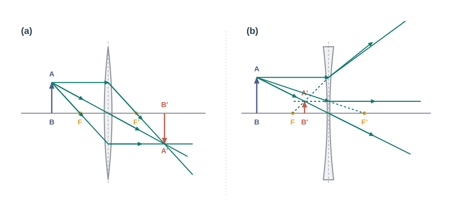
Fig. 9.18 – Ray diagrams for convex and concave lenses.
You should practise drawing such ray diagrams for different object positions, and check that the lens formula, Eq. (9.23), holds in every case. As always, remember that although we draw only two rays, each point of the object actually sends out an infinite number of rays, and all of them pass through the same image point.
The magnification \(m\) produced by a lens is defined, just as for a mirror, as the ratio of the image size to the object size. Working through the geometry in the same way as we did for spherical mirrors gives \[m = \frac{h'}{h} = \frac{v}{u} \tag{9.24}\]
Note carefully that for a lens \(m = v/u\) (with no minus sign), whereas for a mirror \(m = -v/u\). Applying the sign convention, we find that an erect (and therefore virtual) image formed by a convex or concave lens has a positive \(m\), while an inverted (and therefore real) image has a negative \(m\).
9.5.3 Power of a lens
The power of a lens is a measure of how strongly the lens bends light — how much convergence or divergence it produces in the light passing through it. Clearly, a lens with a shorter focal length bends incident light more sharply, converging it in the case of a convex lens and diverging it in the case of a concave lens.
The power \(P\) of a lens is defined as the tangent of the angle by which the lens bends a ray of light that arrives parallel to the principal axis at unit distance from the optical centre (Fig. 9.19).
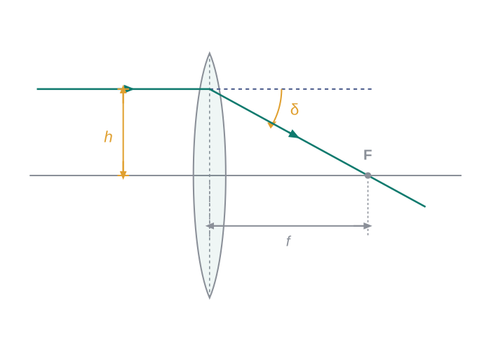
Fig. 9.19 – Defining the power of a lens.
From the geometry, \(\tan\delta = \dfrac{h}{f}\). Setting \(h = 1\) (unit distance) gives \(\tan\delta = \dfrac{1}{f}\), and for small \(\delta\), \(\delta = \dfrac{1}{f}\). Thus the power is \[P = \frac{1}{f} \tag{9.25}\]
The SI unit of power is the dioptre (D), where \(1\ \text{D} = 1\ \text{m}^{-1}\). A lens of focal length 1 metre has a power of one dioptre. The power is taken as positive for a converging (convex) lens and negative for a diverging (concave) lens.
9.5.4 Combination of thin lenses in contact
Consider two thin lenses A and B, of focal lengths \(f_1\) and \(f_2\), placed in contact with each other. Let an object be placed at a point O beyond the focus of the first lens A (Fig. 9.20).
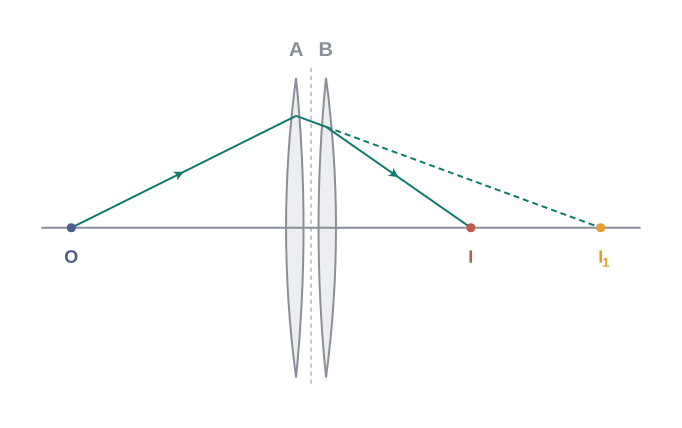
Fig. 9.20 – Image formation by two thin lenses in contact.
The first lens A forms an image at \(I_1\). Since \(I_1\) is a real image, it serves as a virtual object for the second lens B, which then forms the final image at I. (Forming the image \(I_1\) is really just a convenient bookkeeping step; in reality the rays leaving the first lens are immediately intercepted and re-bent by the second.) Because the lenses are thin, we may treat their optical centres as coinciding at a single central point P.
For the image formed by the first lens A, \[\frac{1}{v_1} - \frac{1}{u} = \frac{1}{f_1} \tag{9.27}\]
For the image formed by the second lens B (which uses \(I_1\), at distance \(v_1\), as its object), \[\frac{1}{v} - \frac{1}{v_1} = \frac{1}{f_2} \tag{9.28}\]
Adding Eqs. (9.27) and (9.28), the \(v_1\) terms cancel, leaving \[\frac{1}{v} - \frac{1}{u} = \frac{1}{f_1} + \frac{1}{f_2} \tag{9.29}\]
If we regard the two-lens system as a single equivalent lens of focal length \(f\), then \(\dfrac{1}{v} - \dfrac{1}{u} = \dfrac{1}{f}\), so comparing with Eq. (9.29), \[\frac{1}{f} = \frac{1}{f_1} + \frac{1}{f_2} \tag{9.30}\]
This derivation works for any number of thin lenses in contact. If several lenses of focal lengths \(f_1\), \(f_2\), \(f_3\), … are in contact, the effective focal length of the combination is \[\frac{1}{f} = \frac{1}{f_1} + \frac{1}{f_2} + \frac{1}{f_3} + \dots \tag{9.31}\]
In terms of power, Eq. (9.31) can be written very simply as \[P = P_1 + P_2 + P_3 + \dots \tag{9.32}\] where \(P\) is the net power of the combination.
Note that the sum in Eq. (9.32) is an algebraic sum: some terms are positive (for convex lenses) and some negative (for concave lenses). By combining lenses we can build a system with any desired converging or diverging power and magnification, and we can also improve the sharpness of the image.
Since the image formed by the first lens becomes the object for the second, the total magnification of the combination is the product of the individual magnifications: \[m = m_1 m_2 m_3 \dots \tag{9.33}\]
Find the position of the image formed by the lens combination shown in Fig. 9.21. (The three lenses have focal lengths \(f = +10\) cm, \(-10\) cm, and \(+30\) cm; the object is 30 cm from the first lens, and the lenses are separated by 5 cm and 10 cm.)
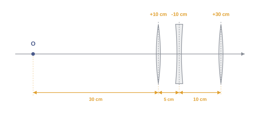
[Caption:] Fig. 9.21 – Ray setup for a three-lens combination. [/Caption:]
Solution:
Image formed by the first lens (using Eq. 9.27):
\[\frac{1}{v_1} - \frac{1}{u_1} = \frac{1}{f_1} \quad\Rightarrow\quad \frac{1}{v_1} - \frac{1}{-30} = \frac{1}{10} \quad\Rightarrow\quad v_1 = 15\ \text{cm}\]
The image formed by the first lens serves as the object for the second lens. It lies at \((15 - 5)\ \text{cm} = 10\) cm to the right of the second lens. Although this image is real, it acts as a virtual object for the second lens (the rays appear to come from it). Then
\[\frac{1}{v_2} - \frac{1}{10} = \frac{1}{-10} \quad\Rightarrow\quad v_2 = \infty\]
So the virtual image is formed at an infinite distance to the left of the second lens. This acts as the object for the third lens:
\[\frac{1}{v_3} - \frac{1}{u_3} = \frac{1}{f_3} \quad\Rightarrow\quad \frac{1}{v_3} = \frac{1}{\infty} + \frac{1}{30} \quad\Rightarrow\quad v_3 = 30\ \text{cm}\]
The final image is formed 30 cm to the right of the third lens.
9.6 Refraction through a Prism
A prism is a transparent block (usually glass) bounded by two flat refracting faces that meet along an edge and are inclined to each other at an angle. We met the prism briefly as a total-internal-reflection device earlier; here we study how it refracts light passing through it.
Figure 9.22 shows a ray of light passing through a triangular prism ABC. The ray PQ enters the first face AB, making an angle of incidence \(i\) and refracting to an angle \(r_1\) inside the glass. It then travels to the second face AC, where it strikes from glass to air with an angle of incidence \(r_2\) and finally leaves the prism as the ray RS, making an angle of refraction (called the angle of emergence) \(e\).
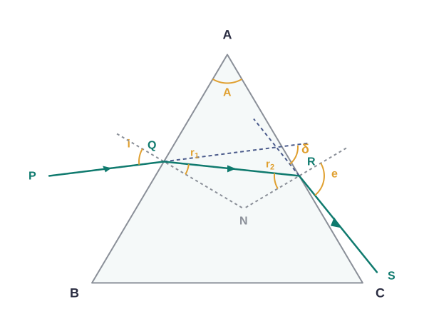
Fig. 9.22 – Refraction through a glass prism.
The angle between the emergent ray RS and the original direction of the incident ray PQ (that is, how much the ray has been turned from its straight path) is called the angle of deviation, \(\delta\).
The angle A between the two refracting faces of the prism is called the refracting angle, or simply the angle of the prism. Let us find how \(\delta\) is related to \(i\), \(e\), and \(A\).
In the quadrilateral AQNR (formed by the two faces and the two normals), the angles at Q and R are right angles, since each normal is perpendicular to its face. The four angles of any quadrilateral add up to \(360^\circ\), so the remaining two angles must sum to \(180^\circ\): \[\angle A + \angle \text{QNR} = 180^\circ\]
Also, from the triangle QNR, \[r_1 + r_2 + \angle \text{QNR} = 180^\circ\]
Comparing these two equations (both equal \(180^\circ\) minus \(\angle\text{QNR}\)) gives the useful relation \[r_1 + r_2 = A \tag{9.34}\]
The total deviation \(\delta\) is simply the sum of the small deviations produced at each of the two faces, \[\delta = (i - r_1) + (e - r_2)\] Using Eq. (9.34) to replace \((r_1 + r_2)\) by \(A\), this becomes \[\delta = i + e - A \tag{9.35}\]
Equation (9.35) shows that the deviation \(\delta\) depends on the angle of incidence \(i\). If we plot \(\delta\) against \(i\), we get the curve shown in Fig. 9.23. Notice that, except at one special point, any particular value of \(\delta\) can be produced by two different angles of incidence.
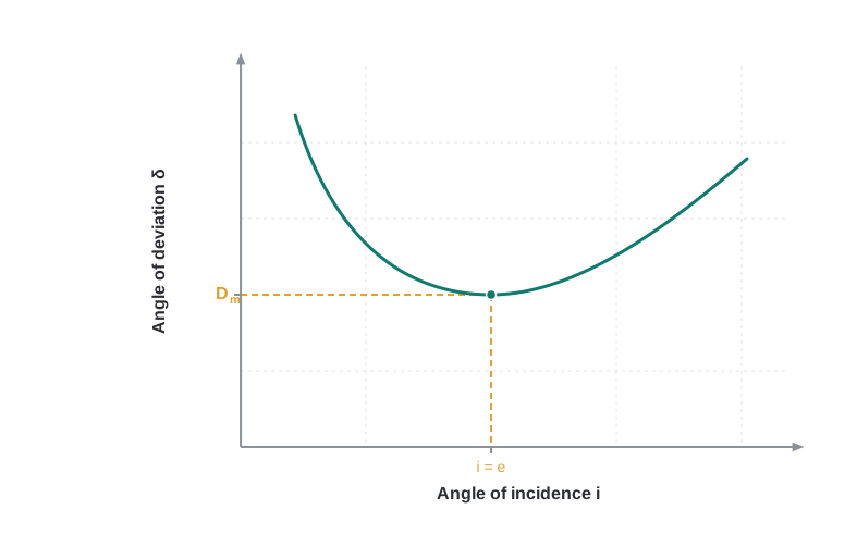
Fig. 9.23 – Angle of deviation versus angle of incidence.
This double-valued behaviour is expected from the symmetry of \(i\) and \(e\) in Eq. (9.35): interchanging \(i\) and \(e\) leaves \(\delta\) unchanged. Physically, this is because the path of the ray through the prism can be exactly reversed, and the reversed path gives the same deviation.
There is one special angle of incidence at which the deviation is smallest. This minimum value is called the angle of minimum deviation, \(D_m\). At minimum deviation, the ray passes symmetrically through the prism — the refracted ray inside the prism runs parallel to the base — so that \(\delta = D_m\), and \(i = e\), which in turn means \(r_1 = r_2\).
Putting \(r_1 = r_2 = r\) into Eq. (9.34) gives \[2r = A \quad \text{or} \quad r = \frac{A}{2} \tag{9.36}\]
Putting \(i = e\) and \(\delta = D_m\) into Eq. (9.35) gives \[D_m = 2i - A, \quad \text{or} \quad i = \frac{A + D_m}{2} \tag{9.37}\]
Now applying Snell’s law at the first face, with angle of incidence \(i\) and refraction angle \(r\), the refractive index of the prism material is \[n_{21} = \frac{n_2}{n_1} = \frac{\sin\left[(A + D_m)/2\right]}{\sin\left[A/2\right]} \tag{9.38}\]
Both the prism angle \(A\) and the angle of minimum deviation \(D_m\) can be measured directly with a simple instrument. So Equation (9.38) gives us a practical method: by measuring how the prism bends the light (the angle \(D_m\)) and the prism’s own angle \(A\), we can calculate the refractive index of the glass — a hidden property of the material itself.
For a prism with a very small refracting angle — a thin prism — the angle of minimum deviation \(D_m\) is also very small. For small angles the sines may be replaced by the angles themselves, so Eq. (9.38) becomes \[n_{21} = \frac{\sin\left[(A + D_m)/2\right]}{\sin\left[A/2\right]} \approx \frac{(A + D_m)/2}{A/2}\] which rearranges to \[D_m = (n_{21} - 1)\,A\] This tells us that a thin prism deviates light only slightly.
9.7 Optical Instruments
Many everyday and scientific devices are built by cleverly combining the reflecting and refracting properties of mirrors, lenses, and prisms that we have studied so far. The periscope, the kaleidoscope, binoculars, telescopes, and microscopes are all familiar examples of such optical instruments.
The most important optical device of all is one that nature has given us — the human eye, which you studied in Class X. In this section we build on the ideas of image formation by lenses to understand the working principles of two key instruments: the microscope and the telescope.
9.7.1 The microscope
A simple magnifier — or simple microscope — is just a single converging lens of small focal length (Fig. 9.24). To use it, the lens is held near the object, at a distance of one focal length or slightly less, and the eye is placed close to the lens on the other side.
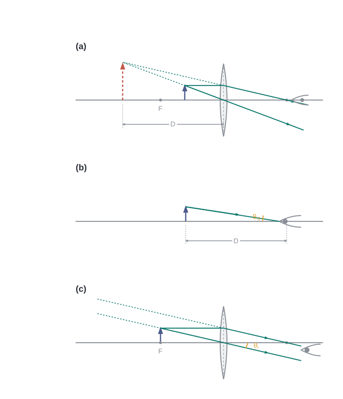
Fig. 9.24 – Working of a simple microscope.
The aim is to produce an erect, magnified, virtual image of the object at a distance where the eye can view it comfortably — that is, at 25 cm or more. This distance of 25 cm is the near point, the closest distance at which a normal eye can see an object clearly without strain. It is denoted by D.
If the object is placed exactly at the focal length (\(u = f\)), the image forms at infinity. If the object is placed a little closer than the focal length, the image is virtual and lies closer than infinity. Viewing the image at the near point gives the largest image but strains the eye slightly; viewing it at infinity is more restful for the relaxed eye. Both arrangements are shown in Fig. 9.24 — the near-point case in (a), and the infinity case in (b) and (c).
Let us first find the linear magnification when the image is formed at the near point D. Using \(m = v/u\) together with the thin lens formula, \[m = \frac{v}{u} = v\left(\frac{1}{v} - \frac{1}{f}\right) = \left(1 - \frac{v}{f}\right)\]
By our sign convention, \(v\) is negative and equal in magnitude to D. Substituting \(v = -D\) gives the magnification \[m = \left(1 + \frac{D}{f}\right) \tag{9.39}\]
Since D is about 25 cm, a magnification of six would need a convex lens of focal length \(f = 5\) cm.
Here \(m = h'/h\) is also the ratio of the angle subtended by the image to the angle the object would subtend if placed at D. (This is not the angle actually subtended by the object at the eye, which is \(h/u\).) What a single-lens magnifier really does is allow the object to be brought much closer to the eye than the near point D, so that it subtends a larger angle.
Now let us find the magnification when the image is formed at infinity, which requires the angular magnification. Suppose the object has height \(h\). The largest angle it can subtend at the unaided eye, while still being seen clearly, is when it is placed at the near point D: \[\tan\theta_o = \left(\frac{h}{D}\right) \approx \theta_o \tag{9.40}\]
With the magnifier, the object is placed at the focus (\(u = -f\)), and the angle subtended at the eye by the image works out to \[\theta_i = \left(\frac{h}{f}\right) \tag{9.41}\]
as is clear from Fig. 9.24(c). The angular magnification is therefore the ratio of these two angles, \[m = \left(\frac{\theta_i}{\theta_o}\right) = \frac{D}{f} \tag{9.42}\]
This value is one less than the near-point magnification of Eq. (9.39), but the viewing is more comfortable and the difference is usually small. From here on, when discussing microscopes and telescopes, we shall assume the final image is formed at infinity.
A simple magnifier is limited to a maximum magnification of about 9 for realistic focal lengths. To achieve much larger magnifications, we use two lenses, one building on the effect of the other. This arrangement is called a compound microscope (Fig. 9.25).
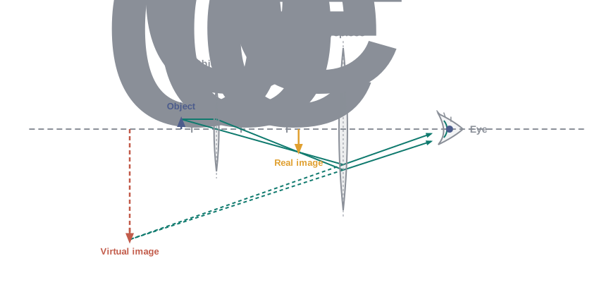
Fig. 9.25 – Ray diagram of a compound microscope.
The lens nearest the object, called the objective, forms a real, inverted, magnified image of the object. This image then acts as the object for the second lens, the eyepiece, which works like a simple magnifier and produces the final image — enlarged and virtual. The first (inverted) image lies at or within the focal plane of the eyepiece, positioned for a final image at infinity (or a little closer, for the near point). The final image is therefore inverted with respect to the original object.
The linear magnification produced by the objective, \(h'/h\), is \[m_o = \frac{h'}{h} = \frac{L}{f_o} \tag{9.43}\] where we have used \(\tan\beta = \left(\dfrac{h}{f_o}\right) = \left(\dfrac{h'}{L}\right)\). Here \(h'\) is the size of the first image, \(h\) the object size, and \(f_o\) the focal length of the objective. The distance L — measured between the second focal point of the objective and the first focal point of the eyepiece (whose focal length is \(f_e\)) — is called the tube length of the compound microscope.
Since the first image lies near the focal point of the eyepiece, we use the simple-microscope result for the angular magnification \(m_e\) of the eyepiece. When the final image is formed at the near point [from Eq. (9.39)], \[m_e = \left(1 + \frac{D}{f_e}\right) \tag{9.44a}\] and when the final image is formed at infinity [from Eq. (9.42)], \[m_e = \left(\frac{D}{f_e}\right) \tag{9.44b}\]
The total magnification is the product of the two [using Eq. (9.33)]. When the image is formed at infinity, \[m = m_o m_e = \left(\frac{L}{f_o}\right)\left(\frac{D}{f_e}\right) \tag{9.45}\]
Clearly, to strongly magnify a small object (hence the name “microscope”), both the objective and the eyepiece should have short focal lengths. In practice it is difficult to make a focal length much smaller than 1 cm, and large lenses are needed to make the tube length L large.
For example, with an objective of \(f_o = 1.0\) cm, an eyepiece of \(f_e = 2.0\) cm, and a tube length of 20 cm, the magnification is \[m = m_o m_e = \left(\frac{L}{f_o}\right)\left(\frac{D}{f_e}\right) = \frac{20}{1} \times \frac{25}{2} = 250\]
Other factors, such as how well the object is illuminated, also affect the quality and visibility of the image. In modern microscopes, both the objective and the eyepiece are actually made of several lenses combined, in order to reduce various optical defects (aberrations).
9.7.2 Telescope
A telescope is used to give an angular magnification of distant objects (Fig. 9.26). Like the microscope, it has an objective and an eyepiece — but here the objective has a large focal length and a much larger aperture (opening) than the eyepiece.
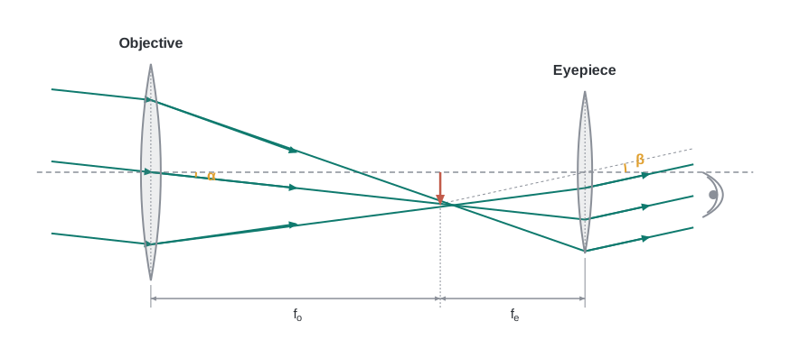
Fig. 9.26 – Ray diagram of a refracting telescope.
Light from a distant object enters the objective, which forms a small real image in the tube at its second focal point. The eyepiece then magnifies this image, producing a final, inverted image. The magnifying power \(m\) is the ratio of the angle \(\beta\) subtended at the eye by the final image to the angle \(\alpha\) that the object subtends at the objective (or the eye). Hence \[m \approx \frac{\beta}{\alpha} \approx \frac{h}{f_e} \cdot \frac{f_o}{h} = \frac{f_o}{f_e} \tag{9.46}\]
In this case, the length of the telescope tube is \(f_o + f_e\) (the objective and eyepiece are separated by the sum of their focal lengths).
Terrestrial telescopes, used to view objects on the ground, include an extra pair of inverting lenses so that the final image is erect. Refracting telescopes can be used for both terrestrial and astronomical observation. For example, a telescope with an objective of focal length 100 cm and an eyepiece of focal length 1 cm has a magnifying power \(m = 100/1 = 100\).
To appreciate what this means, consider a pair of stars whose true angular separation is \(1'\) (one minute of arc). Through this telescope they would appear separated by \(100 \times 1' = 100' = 1.67^\circ\) — a separation now easy for the eye to distinguish.
The two most important qualities of an astronomical telescope are its light-gathering power and its resolving power. The light-gathering power depends on the area of the objective: a larger objective collects more light, so fainter objects can be seen. The resolving power — the ability to see as separate two objects that lie in very nearly the same direction — also improves with the diameter of the objective. This is why the aim in optical telescopes is to make the objective as large in diameter as possible, and it is exactly how a telescope gathers light from faint, distant objects and makes them appear larger and closer.
The largest lens objective ever used has a diameter of 40 inch (about 1.02 m) and is at the Yerkes Observatory in Wisconsin, USA. Such big lenses are very heavy and hard to make and to support by their edges. It is also difficult and expensive to make such large lenses free from colour fringing (chromatic aberration) and other distortions.
For these reasons, modern telescopes use a concave mirror instead of a lens for the objective; these are called reflecting telescopes. A mirror has no chromatic aberration, and it is also easier to support mechanically, since it weighs much less than a lens of equal quality and can be held from its entire back surface rather than only at its rim.
One difficulty with a reflecting telescope is that the objective mirror focuses the light inside the telescope tube, so the eyepiece and observer must sit there and block some of the incoming light. This is what is done in the very large 200 inch (about 5.08 m) Mt. Palomar telescope in California, where the viewer sits in a small cage near the focal point.
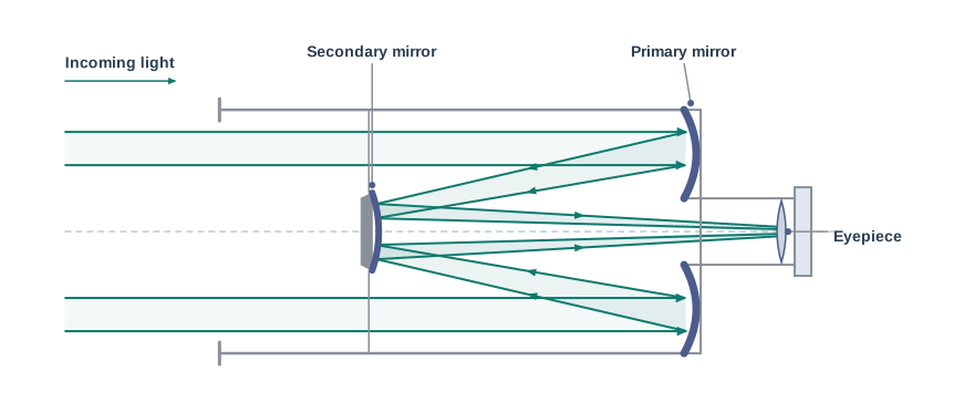
Fig. 9.27 – Schematic of a Cassegrain reflecting telescope.
Another solution is to deflect the focused light with a second mirror. One such design uses a convex secondary mirror to send the light back through a hole in the primary objective mirror, as shown in Fig. 9.27. This is the Cassegrain telescope, named after its inventor, and it has the advantage of packing a long focal length into a short tube. The largest telescope in India, at Kavalur in Tamil Nadu, is a 2.34 m diameter reflecting (Cassegrain) telescope, used by the Indian Institute of Astrophysics, Bangalore. The largest reflecting telescopes in the world are the pair of Keck telescopes in Hawaii, USA, each with a reflector 10 metres in diameter.
9.8 Summary
Reflection and refraction. Reflection follows the rule \(\angle i = \angle r'\) (angle of incidence equals angle of reflection), and refraction follows Snell’s law, \(\dfrac{\sin i}{\sin r} = n\). In both cases the incident ray, the reflected ray, the refracted ray, and the normal at the point of incidence all lie in the same plane. Here \(i\), \(r'\), and \(r\) are the angles of incidence, reflection, and refraction, respectively.
Total internal reflection. The critical angle \(i_c\), for a ray going from a denser to a rarer medium, is the angle of incidence for which the angle of refraction is \(90^\circ\). For \(i > i_c\), total internal reflection occurs. The strong sparkle of diamond (where \(i_c \approx 24.4^\circ\)), totally reflecting prisms, and the mirage are all examples of total internal reflection. Optical fibres consist of glass fibres coated with a thin layer of material of lower refractive index; light entering one end at a suitable angle emerges from the other after many internal reflections, even if the fibre is bent.
Cartesian sign convention. Distances measured in the same direction as the incident light are positive; those measured in the opposite direction are negative. All distances are measured from the pole (mirror) or the optical centre (lens) along the principal axis. Heights measured upwards, above the x-axis and normal to the principal axis, are positive; heights measured downwards are negative.
Mirror equation. \[\frac{1}{v} + \frac{1}{u} = \frac{1}{f}\] where \(u\) and \(v\) are the object and image distances and \(f\) is the focal length. The focal length is (approximately) half the radius of curvature \(R\). Here \(f\) is negative for a concave mirror and positive for a convex mirror.
Prism. For a prism of refracting angle \(A\), made of a material of refractive index \(n_2\) placed in a medium of refractive index \(n_1\), \[n_{21} = \frac{n_2}{n_1} = \frac{\sin\left[(A + D_m)/2\right]}{\sin\left[A/2\right]}\] where \(D_m\) is the angle of minimum deviation.
Refraction by spherical surfaces and lenses. For refraction through a single spherical interface (from medium 1 to medium 2, of refractive indices \(n_1\) and \(n_2\)), \[\frac{n_2}{v} - \frac{n_1}{u} = \frac{n_2 - n_1}{R}\] The thin lens formula is \[\frac{1}{v} - \frac{1}{u} = \frac{1}{f}\] and the lens maker’s formula is \[\frac{1}{f} = \frac{(n_2 - n_1)}{n_1}\left(\frac{1}{R_1} - \frac{1}{R_2}\right)\] where \(R_1\) and \(R_2\) are the radii of curvature of the two lens surfaces. Here \(f\) is positive for a converging lens and negative for a diverging lens. The power of a lens is \(P = 1/f\), and its SI unit is the dioptre (D), where \(1\ \text{D} = 1\ \text{m}^{-1}\). If several thin lenses of focal lengths \(f_1\), \(f_2\), \(f_3\), … are in contact, the effective focal length of the combination is \[\frac{1}{f} = \frac{1}{f_1} + \frac{1}{f_2} + \frac{1}{f_3} + \dots\] and the total power is \[P = P_1 + P_2 + P_3 + \dots\]
Dispersion. Dispersion is the splitting of light into its constituent colours.
Microscope. The magnifying power of a simple microscope is \(m = 1 + (D/f)\), where \(D = 25\) cm is the least distance of distinct vision and \(f\) is the focal length of the convex lens; if the image is at infinity, \(m = D/f\). For a compound microscope, the magnifying power is \(m = m_e \times m_o\), where \(m_e = 1 + (D/f_e)\) is the magnification due to the eyepiece and \(m_o\) is the magnification produced by the objective. Approximately, \[m = \frac{L}{f_o} \times \frac{D}{f_e}\] where \(f_o\) and \(f_e\) are the focal lengths of the objective and eyepiece, and \(L\) is the distance between their focal points.
Telescope. The magnifying power of a telescope is the ratio of the angle \(\beta\) subtended at the eye by the image to the angle \(\alpha\) subtended at the eye by the object: \[m = \frac{\beta}{\alpha} = \frac{f_o}{f_e}\] where \(f_o\) and \(f_e\) are the focal lengths of the objective and eyepiece, respectively.
9.9 Points to Ponder
The laws of reflection and refraction are true for every surface and every pair of media, applied right at the point of incidence. They are local rules — they hold at each individual point where a ray meets a surface, no matter how the surface as a whole is shaped.
The real image of an object placed between \(f\) and \(2f\) from a convex lens can be caught on a screen placed at the image position. But now ask: if the screen is removed, is the image still there? This puzzles many people, because it is hard to accept an image “hanging” in mid-air with no screen. Yet the image really does exist. Rays from each point of the object are genuinely converging to an image point in space and then diverging away from it. A screen does nothing to create the image; it merely scatters those rays so that some of them reach our eyes and we see it. You can actually observe such images formed in mid-air during a laser show.
Image formation needs regular (orderly) reflection or refraction. For a sharp image, all the rays leaving a single point of the object must arrive at a single image point. This is why you cannot see your reflection in an irregular surface — for example, the page of a book scatters light in all directions, so the rays never regroup into an image.
Thick lenses produce coloured images because of dispersion — the slight difference in how much each colour is bent. More broadly, the variety of colours we see in the objects around us comes from the different colours present in the light falling on them. The very same object can look completely different in colour under a single-colour (monochromatic) light than it does in ordinary white light.
For a simple microscope, the angular size of the object equals the angular size of the image — so where does the magnification come from? The gain is that the magnifier lets us hold the small object much closer to the eye than 25 cm, so it subtends a large angle, while the image it forms sits comfortably at about 25 cm where we can see it clearly. Without the magnifier, we would have to keep the small object at 25 cm, where it would subtend only a tiny angle and appear very small.
9.10 NCERT Questions
A small candle, 2.5 cm in size, is placed 27 cm in front of a concave mirror of radius of curvature 36 cm. At what distance from the mirror should a screen be placed in order to obtain a sharp image? Describe the nature and size of the image. If the candle is moved closer to the mirror, how would the screen have to be moved?
A 4.5 cm needle is placed 12 cm away from a convex mirror of focal length 15 cm. Give the location of the image and the magnification. Describe what happens as the needle is moved farther from the mirror.
A tank is filled with water to a height of 12.5 cm. The apparent depth of a needle lying at the bottom of the tank is measured by a microscope to be 9.4 cm. What is the refractive index of water? If water is replaced by a liquid of refractive index 1.63 up to the same height, by what distance would the microscope have to be moved to focus on the needle again?
Figures 9.28(a) and (b) show refraction of a ray in air incident at 60° with the normal to a glass-air and a water-air interface, respectively. Predict the angle of refraction in glass when the angle of incidence in water is 45° with the normal to a water-glass interface [Fig. 9.28(c)].
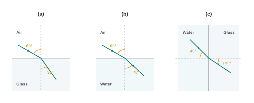
Fig. 9.28 – Ray refractions across three different interfaces.
A small bulb is placed at the bottom of a tank containing water to a depth of 80 cm. What is the area of the surface of water through which light from the bulb can emerge out? Refractive index of water is 1.33. (Consider the bulb to be a point source.)
A prism is made of glass of unknown refractive index. A parallel beam of light is incident on a face of the prism. The angle of minimum deviation is measured to be 40°. What is the refractive index of the material of the prism? The refracting angle of the prism is 60°. If the prism is placed in water (refractive index 1.33), predict the new angle of minimum deviation of a parallel beam of light.
Double-convex lenses are to be manufactured from a glass of refractive index 1.55, with both faces of the same radius of curvature. What is the radius of curvature required if the focal length is to be 20 cm?
A beam of light converges at a point P. Now a lens is placed in the path of the convergent beam 12 cm from P. At what point does the beam converge if the lens is (a) a convex lens of focal length 20 cm, and (b) a concave lens of focal length 16 cm?
An object of size 3.0 cm is placed 14 cm in front of a concave lens of focal length 21 cm. Describe the image produced by the lens. What happens if the object is moved further away from the lens?
What is the focal length of a convex lens of focal length 30 cm in contact with a concave lens of focal length 20 cm? Is the system a converging or a diverging lens? Ignore the thickness of the lenses.
A compound microscope consists of an objective lens of focal length 2.0 cm and an eyepiece of focal length 6.25 cm separated by a distance of 15 cm. How far from the objective should an object be placed in order to obtain the final image at (a) the least distance of distinct vision (25 cm), and (b) at infinity? What is the magnifying power of the microscope in each case?
A person with a normal near point (25 cm) using a compound microscope with an objective of focal length 8.0 mm and an eyepiece of focal length 2.5 cm can bring an object placed at 9.0 mm from the objective into sharp focus. What is the separation between the two lenses? Calculate the magnifying power of the microscope.
A small telescope has an objective lens of focal length 144 cm and an eyepiece of focal length 6.0 cm. What is the magnifying power of the telescope? What is the separation between the objective and the eyepiece?
- A giant refracting telescope at an observatory has an objective lens of focal length 15 m. If an eyepiece of focal length 1.0 cm is used, what is the angular magnification of the telescope?
- If this telescope is used to view the moon, what is the diameter of the image of the moon formed by the objective lens? The diameter of the moon is \(3.48 \times 10^{6}\) m, and the radius of the lunar orbit is \(3.8 \times 10^{8}\) m.
Use the mirror equation to deduce that:
- an object placed between \(f\) and \(2f\) of a concave mirror produces a real image beyond \(2f\);
- a convex mirror always produces a virtual image independent of the location of the object;
- the virtual image produced by a convex mirror is always diminished in size and is located between the focus and the pole;
- an object placed between the pole and focus of a concave mirror produces a virtual and enlarged image.
A small pin fixed on a tabletop is viewed from above from a distance of 50 cm. By what distance would the pin appear to be raised if it is viewed from the same point through a 15 cm thick glass slab held parallel to the table? Refractive index of glass = 1.5. Does the answer depend on the location of the slab?
- Figure 9.29 shows a cross-section of a ‘light pipe’ made of a glass fibre of refractive index 1.68. The outer covering of the pipe is made of a material of refractive index 1.44. What is the range of the angles of the incident rays with the axis of the pipe for which total internal reflections inside the pipe take place, as shown in the figure?
- What is the answer if there is no outer covering on the pipe?
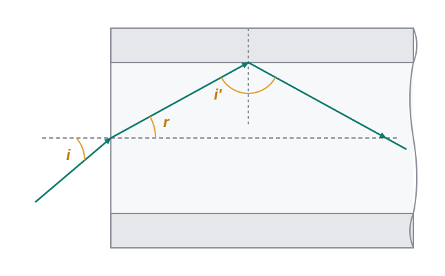
Fig. 9.29 – Refraction and reflection in a light pipe.
The image of a small electric bulb fixed on the wall of a room is to be obtained on the opposite wall, 3 m away, by means of a large convex lens. What is the maximum possible focal length of the lens required for the purpose?
A screen is placed 90 cm from an object. The image of the object on the screen is formed by a convex lens at two different locations separated by 20 cm. Determine the focal length of the lens.
- Determine the ‘effective focal length’ of the combination of the two lenses in Question 10, if they are placed 8.0 cm apart with their principal axes coincident. Does the answer depend on which side of the combination a beam of parallel light is incident? Is the notion of effective focal length of this system useful at all?
- An object 1.5 cm in size is placed on the side of the convex lens in the arrangement (a) above. The distance between the object and the convex lens is 40 cm. Determine the magnification produced by the two-lens system, and the size of the image.
At what angle should a ray of light be incident on the face of a prism of refracting angle 60° so that it just suffers total internal reflection at the other face? The refractive index of the material of the prism is 1.524.
A card sheet divided into squares each of size 1 mm² is being viewed at a distance of 9 cm through a magnifying glass (a converging lens of focal length 9 cm) held close to the eye.
- What is the magnification produced by the lens? How much is the area of each square in the virtual image?
- What is the angular magnification (magnifying power) of the lens?
- Is the magnification in (a) equal to the magnifying power in (b)? Explain.
- At what distance should the lens be held from the card sheet in Question 22 in order to view the squares distinctly with the maximum possible magnifying power?
- What is the magnification in this case?
- Is the magnification equal to the magnifying power in this case? Explain.
What should be the distance between the object in Question 23 and the magnifying glass if the virtual image of each square in the figure is to have an area of 6.25 mm²? Would you be able to see the squares distinctly with your eyes very close to the magnifier?
Answer the following questions:
- The angle subtended at the eye by an object is equal to the angle subtended at the eye by the virtual image produced by a magnifying glass. In what sense, then, does a magnifying glass provide angular magnification?
- In viewing through a magnifying glass, one usually positions one’s eyes very close to the lens. Does the angular magnification change if the eye is moved back?
- The magnifying power of a simple microscope is inversely proportional to the focal length of the lens. What then stops us from using a convex lens of smaller and smaller focal length and achieving greater and greater magnifying power?
- Why must both the objective and the eyepiece of a compound microscope have short focal lengths?
- When viewing through a compound microscope, our eyes should be positioned not on the eyepiece but a short distance away from it for best viewing. Why? How much should be that short distance between the eye and the eyepiece?
An angular magnification (magnifying power) of 30X is desired using an objective of focal length 1.25 cm and an eyepiece of focal length 5 cm. How will you set up the compound microscope?
A small telescope has an objective lens of focal length 140 cm and an eyepiece of focal length 5.0 cm. What is the magnifying power of the telescope for viewing distant objects when
- the telescope is in normal adjustment (i.e., when the final image is at infinity)?
- the final image is formed at the least distance of distinct vision (25 cm)?
- For the telescope described in Question 27(a), what is the separation between the objective lens and the eyepiece?
- If this telescope is used to view a 100 m tall tower 3 km away, what is the height of the image of the tower formed by the objective lens?
- What is the height of the final image of the tower if it is formed at 25 cm?
A Cassegrain telescope uses two mirrors as shown in Fig. 9.27. Such a telescope is built with the mirrors 20 mm apart. If the radius of curvature of the large mirror is 220 mm and that of the small mirror is 140 mm, where will the final image of an object at infinity be?
Light incident normally on a plane mirror attached to a galvanometer coil retraces its path backwards, as shown in Fig. 9.30. A current in the coil produces a deflection of 3.5° of the mirror. What is the displacement of the reflected spot of light on a screen placed 1.5 m away?
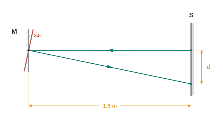
Fig. 9.30 – Optical lever in a galvanometer.
- Figure 9.31 shows an equiconvex lens (of refractive index 1.50) in contact with a liquid layer on top of a plane mirror. A small needle, with its tip on the principal axis, is moved along the axis until its inverted image is found at the position of the needle. The distance of the needle from the lens is measured to be 45.0 cm. The liquid is removed and the experiment is repeated. The new distance is measured to be 30.0 cm. What is the refractive index of the liquid?
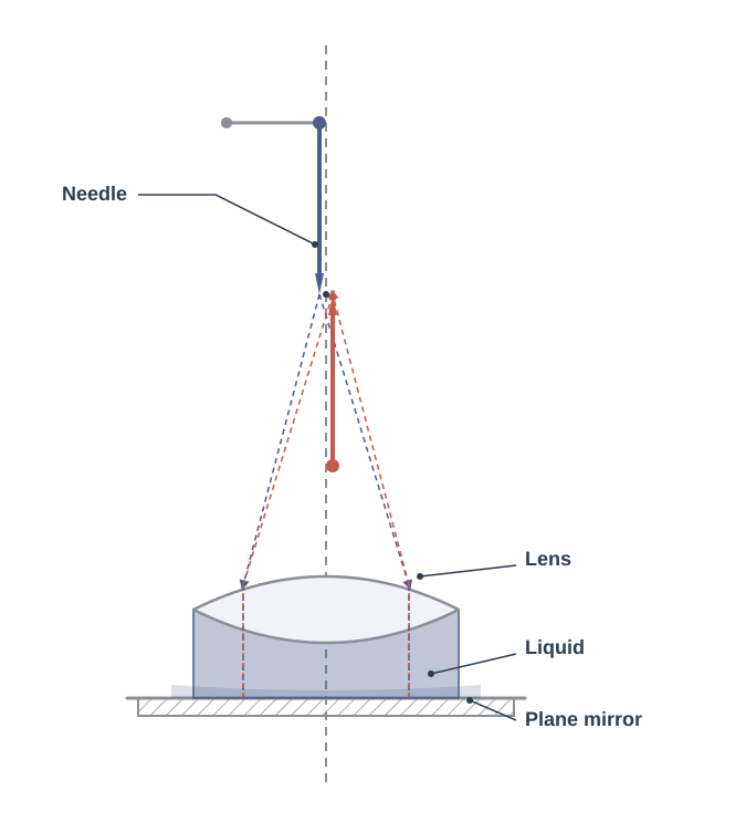
Fig. 9.31 – Lens over a liquid layer on a plane mirror.
9.11 Check Your Concepts
Explain why the normal to a spherical mirror at any point always passes through its centre of curvature. Use this to justify why a ray directed towards the centre of curvature of a concave mirror retraces its path after reflection.
A convex mirror is used as a rear-view mirror in vehicles rather than a plane or concave mirror. Giving reasons based on the nature and size of the image formed by a convex mirror, explain this choice. What is the one disadvantage of using it?
“Total internal reflection can occur only when light travels from a denser medium into a rarer medium.” Explain why this condition is essential, and describe what happens to a ray that goes instead from a rarer medium into a denser one.
A glass lens has a certain focal length in air. When the same lens is placed in water, its focal length increases considerably. Explain, using the lens maker’s formula, why the focal length changes when the surrounding medium changes.
A prism deviates a beam of white light and also spreads it into a band of colours. Explain (i) why the beam is deviated towards the base of the prism, and (ii) why the different colours are deviated by different amounts.
Modern large astronomical telescopes use a concave mirror rather than a lens for the objective. Give two distinct reasons why a mirror objective is preferred over a lens objective for very large telescopes.
The magnification produced by a mirror is \(m = -v/u\), while that produced by a lens is \(m = +v/u\). For each case, state what the sign of \(m\) tells you about the orientation (erect or inverted) and the type (real or virtual) of the image.
A swimming pool always appears shallower than it really is when viewed from above. Using the idea of apparent depth, explain this observation and state how the apparent depth is related to the real depth and the refractive index of water.
An optical fibre continues to guide light along its length even when it is bent into a curve. Explain, in terms of total internal reflection and the refractive indices of the core and cladding, how this is possible.
9.12 Practice with Numericals
An object 3.0 cm tall is placed 45 cm in front of a concave mirror of focal length 15 cm. Find the position, nature, and size of the image formed.
A ray of light travelling in air is incident on the surface of water at an angle of incidence of 40°. If the refractive index of water is 1.33, find the angle of refraction inside the water.
The refractive index of a certain glass with respect to air is 1.52. Find the critical angle for a ray of light passing from this glass into air.
A pin is placed at the bottom of a beaker filled with a transparent liquid to a depth of 15 cm. When viewed from directly above, the pin appears to be at a depth of 10 cm. Find the refractive index of the liquid.
A double convex lens has both surfaces of radius of curvature 25 cm and is made of glass of refractive index 1.5. Using the lens maker’s formula, find its focal length and its power in dioptres.
A convex lens of power \(+4.0\) D is placed in contact with a concave lens of power \(-2.5\) D. Find the net power of the combination and the focal length of the equivalent single lens. State whether the combination is converging or diverging.
A prism of refracting angle 60° is made of a material whose angle of minimum deviation is 30°. Find the refractive index of the material of the prism.
A simple microscope (magnifying glass) has a focal length of 5 cm. Taking the near point as 25 cm, find its magnifying power (a) when the final image is formed at the near point, and (b) when the final image is formed at infinity.
An astronomical telescope has an objective of focal length 100 cm and an eyepiece of focal length 2.5 cm. For a distant object with the final image formed at infinity, find (a) the magnifying power of the telescope, and (b) the length of the telescope tube.